Comparing biaxial geogrids of different formsIntroductionFor 25 years all geogrids were constructed from square or rectangular openings with many universally approved and established test methods for comparing the key design properties and publicly presented papers discussing the merits of the available products. However, since 2007 geogrids with a variety of different-shaped apertures have been available. The technical need for a new form of geogrid is unsubstantiated & their performance is largely unproven. Furthermore, their triangular form means that their properties cannot be established using the existing & established test methods. Little or no publicly available information exists to enable users to reach an informed decision on how such a product will compare to existing products with proven performance. Additionally, the lack of comparable data poses designers with a difficulty in fulfilling their duty of being able to specify a product (directly or generically) ‘or similar approved’ Concerned by these anomalies. We wanted to address the issue to establish the performance of triangular grid relative to our own E’GRID range, by looking at the 3 fundamental and generally accepted performance criteria:
Rib formTo mobilise the granular interlock necessary for a geogrid to perform its reinforcement function the sub-grade must be able to lock up against the ribs of the geogrid and transfer load into the geogrid. A higher vertical rib provides a greater surface area and hence more effectively transfers the stresses. From this, it follows that products with a lesser rib height will transfer the stresses less effectively. It is believed that products having lesser rib heights can actually twist / buckle in the soil such that they do not remain flat as intended. Such an occurrence would have a significant adverse effect on performance. E’GRID geogrids have been designed to optimise the rib height when the polymer sheet is punched and drawn.  The sections above show the machine direction (MD) and transverse direction (TD) ribs of E’GRID (prefixed S) and Triax (prefixed T) geogrids. The diagrams show that both types of geogrid have good rib height and will hence give efficient load transfer. The left-hand diagram compares E’GRID 2020 and Triax TX160. Both have similar rib forms so it can be assumed they would perform in a similar manner. The right-hand diagram compares E’GRID 3030 and Triax TX170. Here it can be clearly seen that the E’GRID 3030 has a significantly greater rib height so it can be assumed the product would provide superior performance. Given the importance of rib height to a product's performance this measure should be included in a geogrid specification. Rib height thickness
Durability (Resistance to installation damage)For a product to perform well for its design life it must retain as much of its original strength as possible when subjected to the, not insignificant, installation stresses of compacting the granular layers above the product. To evaluate this, full-scale trials were undertaken in accordance with Annex D of BS8006-2010 using 3 graded crushed rock fills (5mm, 60mm, 125mm maximum stone size). Differing grades of E’GRID and Triax geogrids were installed as if they were being used in the construction of a carriageway with the 3 different rock fills. They were then excavated and their strengths were measured and recorded relative to their original properties. The table below shows clearly for all of the stone sizes that both of the triangular-aperture geogrids tested are more susceptible to Installation Damage than even the lightest square-aperture geogrid.
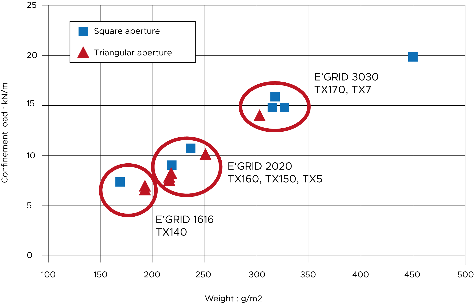
Tensile propertiesSince it was not possible to compare tensile properties using existing test methods a new test was required. This was achieved by developing an existing German test (DIN 61551) for comparing geomembranes and an American test (ASTM D5617) for using an impermeable membrane underneath a permeable product that is being tested. Results are recorded at 2% strain as this is reasonably close to in-field working conditions whilst being large enough to achieve measurable laboratory results. Providing results ‘omnidirectionally’ in the X-Y plane, the test places all of the ribs under equal strain and better represents the plate loading effect of a wheel load travelling along a carriageway. The graph below plots test results for a range of samples.  This graph shows three areas of comparison from which the conclusions below can be drawn.
Related pagesRelated products
| ||||||||||||||||||||||||||||||||||||||||||||||||||||||||||||||||||||||||||||||||
